Circuit design
1. Polar solid aluminum capacitors have positive and negative electrodes. Do not reverse the solid aluminum capacitors. Reverse solid aluminum capacitors can cause a sharp increase in leakage current or a decrease in service life.
2. Circuits that are forbidden to use: Even if the customer installs a solid aluminum capacitor in strict accordance with the welding conditions we have given, the leakage current of the solid aluminum capacitor may increase or even increase significantly. High temperature no load test, high temperature and high humidity no load test, temperature rapid change test, etc. may lead to an increase in leakage current. Therefore, do not apply solid aluminum capacitors to circuits that are sensitive to leakage currents. such as:
a) high impedance circuit;
b) a coupling circuit;
c) Time constant circuit.
3. Working voltage
a) The sum of the DC voltage and the ripple peak voltage shall not exceed the rated operating voltage;
b) When the DC voltage is relatively low, the reverse ripple peak voltage cannot exceed 10% of the rated operating voltage;
c) For products above 25v, when the ambient temperature exceeds 85 °C, please use a solid aluminum capacitor for depressurization. For every 10 °C rise in temperature, the voltage applied to the product should be reduced by 10%.
4. Please select a suitable solid capacitor according to the capacitance characteristics specified in the specification.
a) Do not use over voltage, even a short overvoltage may cause a short circuit of the solid capacitor;
b) the ambient temperature used must be within the range specified in the specification;
c) Do not apply more than the rated ripple current to the solid capacitor. Excessive ripple current will cause excessive heat inside the capacitor, which may lead to premature failure or even short circuit.
5. Instantaneous charge and discharge:
Instantaneous charge and discharge may cause a short circuit in the solid aluminum capacitor or increase the leakage current, so design the protection circuit in the following situations:
a) The inrush current is greater than 10A;
b) The inrush current is greater than 10 times the allowable ripple current value. In addition, when testing the product leakage current, please set a 1kΩ protection resistor.
6. Failure mode and life
a) Accidental failure: mainly caused by short circuit of the circuit. When the current in the short circuit exceeds 1A, the internal temperature of the capacitor will rise, the internal pressure will increase, the sealing rubber will be raised or even opened, and the capacitor will release harmful gases. Please leave this occasion at this time;
b) Life failure: After long-term use, the characteristics of solid aluminum capacitors will be attenuated, such as capacity drop, ESR rise, etc. When the use time exceeds the rated life, the characteristics of the capacitor deteriorate, and electrolyte insulation may be caused. This is called open circuit failure mode. .
c) Solid capacitor life calculation formula
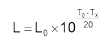
In the formula:
L: life expectancy at a certain temperature [h]
L0: rated life [h]
T0: Maximum rated operating temperature [°C]
Tx: actual ambient temperature [°C]
special reminder
1. Leakage current:
The welding heat and the mechanical stress originating from the transportation can cause the leakage current of the capacitor to increase. However, applying a DC voltage not exceeding the rated working voltage to the product gradually reduces the leakage current, and does not exceed the rated working voltage and the working upper limit temperature. Under the premise, the higher the applied voltage and the higher the ambient temperature, the faster the leakage current decreases.
2. Capacitor insulation:
The insulating coating or insulating hose layer outside the capacitor is not absolutely insulated, and the aluminum shell and the negative lead wire are not insulated. When installing, be sure to completely separate the aluminum casing, positive and negative guide pins and PC board prints.
3. Working environment restrictions:
Do not use solid aluminum capacitors in the following environments:
a) water, salt water, where oil can drip directly, and boards that are prone to shrinkage;
b) where harmful gases (H2S, sulfuric acid, nitric acid, ammonia, hydrochloric acid, etc.) are concentrated;
c) In the case of ultraviolet radiation, radioactive rays, ozone, etc.
4. PCB board design
a) Do not install solid capacitors around or above the heat source components;
b) The mounting hole diameter and spacing on the PCB should match the diameter and pitch of the capacitor pins.
5. Parallel circuit: When the solid capacitor is connected in parallel with another (liquid) capacitor, since the solid capacitor has a much lower ESR value, a large ripple current may be applied to the solid capacitor. Be sure to carefully select the specifications of the capacitor.
6. The electrical performance of solid aluminum capacitors is affected by frequency fluctuations. This factor should be considered when designing the circuit.
7. When installing a solid aluminum capacitor on a double-sided PCB, do not install a solid aluminum capacitor at the perforation of the PCB before and after the connection.
Preparation before installation
1. Soldering: Please weld according to the welding conditions specified in SPEC. Otherwise, it may cause damage to the outer insulation layer, sharp increase of leakage current and decrease in capacity;
2. Precautions before installation:
a) Please do not reuse the solid aluminum capacitor that has been installed and used;
b) When the storage time of the solid aluminum capacitor is long, the leakage current will increase. At this time, the capacitor can be subjected to a voltage treatment. The recommended processing conditions are: 60~70°C rated voltage for 1 hour, and the capacitor is connected in series with 1kΩ protection resistor. .
3. Installation:
a) carefully check the capacitor's capacity and operating voltage;
b) Please pay attention to the polarity of the capacitor;
c) Please be careful not to drop the solid aluminum capacitor on the ground, and do not use the dropped capacitor;
d) Do not deform the solid aluminum capacitor;
e) Before installation, please check whether the capacitor pin type matches the hole diameter and spacing on the PCB. When using the automatic inserter, please do not use too much insertion force;
f) Please pay attention to the vibration intensity generated by the automatic insertion and installation machine, product inspection equipment, etc.;
g) Do not apply additional external force to the capacitor guide pins and the capacitor itself.
4. When soldering with a soldering iron:
a) Please set the welding conditions (temperature, time) according to the specifications of the capacitor;
b) When the type of the guide pin of the solid aluminum capacitor does not match the PCB board, when the guide pin has to be processed, please handle it before welding so as not to leave stress on the solid aluminum capacitor after soldering;
c) Do not apply additional stress to the solid aluminum capacitor when soldering;
d) When removing a poorly mounted solid aluminum capacitor from the board with an electric soldering iron, make sure that the soldering iron has completely melted the solder before removing the solid aluminum capacitor to avoid stress on the solid aluminum capacitor;
e) Do not touch the head of the soldering iron to a solid aluminum capacitor;
f) After welding, the leakage current of the solid aluminum capacitor may increase, and the leakage current will gradually decrease after the voltage is applied.
5. Wave soldering
a) Please do not submerge the solid aluminum capacitor in the solder. Please solder the opposite side of the solid aluminum capacitor on the PCB board;
b) Please set the welding conditions (temperature, time) according to the specifications of the capacitor;
c) After welding, the leakage current of the solid aluminum capacitor may increase, and the leakage current will gradually decrease after the voltage is applied;
d) Please be careful not to touch the solder in any part other than the guide pin;
e) When soldering, please note that other components on the board do not touch the solid aluminum capacitor or drop onto the solid aluminum capacitor;
f) When an extremely abnormal soldering process is used, it may cause the capacity of the solid aluminum capacitor to drop or damage other characteristics of the capacitor.
The following welding processes are recommended:

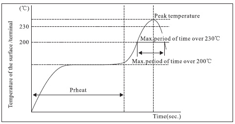
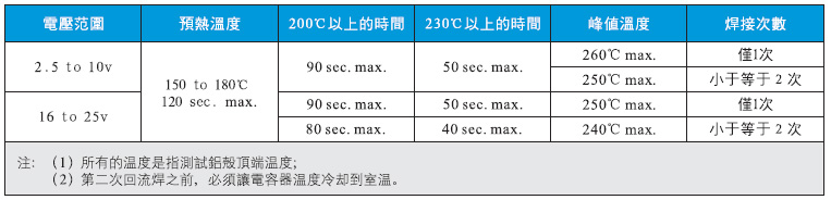
6. Reflow soldering
For SMD type solid aluminum capacitor products, the recommended reflow conditions are:
7. Precautions after welding
a) When the solid aluminum capacitor is soldered, do not use external force to tilt, bend or twist it;
b) Please do not grab the solid aluminum capacitor to move the PCB board;
c) When stacking PCB boards with solid aluminum capacitors, do not touch or contact solid aluminum capacitors with other components;
d) Do not allow external aluminum capacitors soldered on the PCB to withstand external forces.
8. PCB board cleaning: Please choose ethanol cleaning agent, and pay attention to the following conditions:
a) When using immersion method and ultrasonic cleaning, please do not exceed 2 minutes;
b) the cleaning temperature must be lower than 60 ° C;
c) Please pay attention to the pollution caused by cleaning agents;
d) After cleaning, dry with hot air below the rated working temperature.
9. Other notes:
a) Do not touch the lead wire of the solid aluminum capacitor directly with your hand;
b) Do not use a conductor to connect the positive and negative poles of a solid aluminum capacitor. Do not allow the solid aluminum capacitor to contact a conductive solution (such as an aqueous solution of acid and helium);
Storage and disposal
Storage condition
a) Do not store solid aluminum capacitors in a high temperature and high humidity environment, a good storage temperature of 5 ~ 35 ° C, humidity of 75% or less;
b) In order to maintain good solderability of solid aluminum capacitors, please do not open the factory packaging, and the storage period should not exceed 1 year;
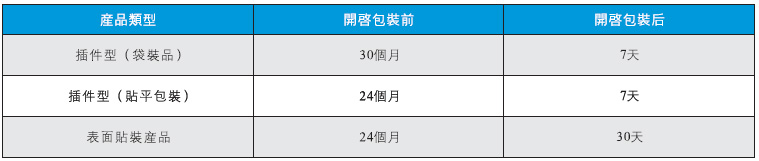
c) Open the package only before installation and install the entire product at one time. If there is any product remaining, please put it back in the bag and seal the bag. Please refer to the following table for the storage period of each type of product:
d) Do not store solid aluminum capacitors in a hazardous atmosphere.
2. Disposal of waste products
Because solid aluminum capacitors contain some solid organic matter, some metal materials, and resin materials, please dispose of the discarded solid aluminum capacitors as industrial waste.
Restriction of Hazardous Substances (RoHS)
The Barry products comply with the European Union's requirements for the use of hazardous substances, and we guarantee that our products do not contain a range of substances beyond the RoHS Directive in the table below:
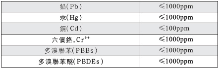
Halogen-free declaration
The Barry products meet the halogen content limits listed in the table below:





 QQ咨询
 在线客服